Hammond Generator Filters

General Description

From the Service Manual:

As a means of eliminating any vagrant harmonics that may be present, there are filters consisting of small transformers and condensers associated with certain frequencies. The transformers have a single tapped winding, and this tap is grounded, so one side, which is connected to the corresponding magnet coil through a condenser, forms a resonant circuit for the fundamental frequency of that coil. This tends to emphasize the fundamental and suppress harmonics.

These transformers and condensers are mounted on the top of the generator assembly. The transformers are mounted at an angle, thus minimizing the interference between them. The cores of the transformers are made of a special iron, and the number of laminations used is adjusted to secure the proper inductance. Wire from the magnet coils connect to the transformers, and wires from the transformers lead to the terminal strip on the generator.

Transformers and condensers are not used below frequency 44, but a length of resistance wire shunts each generator. Frequencies 44 to 48 have transformers only, while both transformers and condensers are used for frequencies 49 to 91 except in the case of the Model A consoles numbered below 2179, which do not have condensers for frequencies 49 to 54 inclusive.

Two condenser values are used – 0.255 mfd for frequencies 49 to 54, and 0.105 mfd for frequencies 55 to 91. The transformers are all different. Each transformer is matched to its condenser and any replacements are supplied as matched pairs by the factory.


If you have a dead note on your generator you may suspect a bad filter. Be sure to eliminate other possibilities.

Mechanical

Make sure the wires are securely connected to the filter circuit.

The wiring of the filter is rather simple but not always easy to get to. Once you have determined which filter is suspect, trace the wires from the pick-up coil to the filter and then to the output terminal. A common problem is a capacitor lead will break from frequent moving of the organ. This will stop the note from sounding.

Hammond Generator Filters

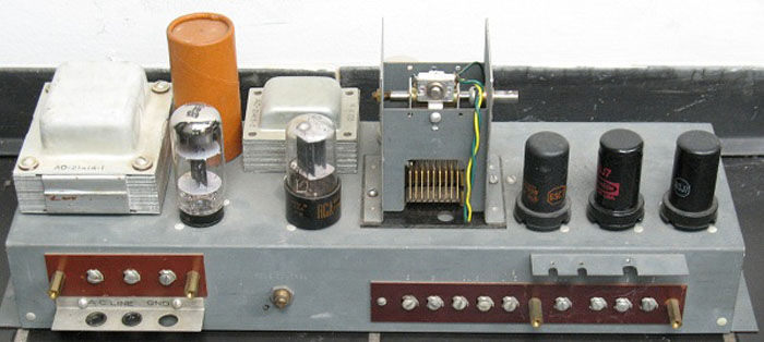
Notice in the above picture there is a pair of very small copper colored magnet wires which comes from the filter coil and solders to a tab sticking up from the generator filter cover. These tabs are seen just to the right of each orange wire. This is the center tap ground of the filter transformer. If this wire breaks you will lose nearly all output from that tone.

Electrical

Pickup Coil
Pickup Coil


The above diagram shows the signal flow. The tone originates in the pick-up coil and is sent to the series capacitor, then into the filter coil and to the output terminal. You can see the ground in the middle of the coil. This circuit sets up a resonant filter which emphasizes the fundamental frequency and filters out the harmonics.

Pickup Coil 2
Pickup Coil

The next diagram shows a different type of filter used on a lower group of tones in frequency and notice there is no series capacitor.

Pickup Coil 3
Pickup Coil

In the last type you will see that no filter is necessary for these tones. A resistor to ground is the only component.

Troubleshooting

For tracing a tone through this circuit you can clip a lead onto the back of a drawbar. Make sure the drawbar is enabled with it’s preset turned on and make sure the drawbar is pulled out about halfway. Take the other end of the clip lead and touch it to the terminals on the generator. When you find a dead terminal follow the wire from that terminal to it’s filter circuit. Touch the terminals on the filter circuit and see if the signal is present on the pick-up coil side of the filter. This is a great and simple tool for tracing signals. On a working filter you will notice that the signal before the filter sounds quite different from the signal on it’s output. You can actually hear what the filter is doing!


Filter Updates

On later model Hammonds additional filters were added to eliminate background hum. Below is a diagram from an H-100 manual showing the factory updated filters.
Filter Update
Filter Update
C1 and the 1000 ohm resistor adds a high pass filter section to reduce the lower rumble or hum in the tone. Below is the chart with the values of C1 for each group of filters.
49 50 51
10 mfd
52 53 54
9 mfd
55 56 57
8 mfd
58 59 60
7 mfd
61 62 63
5 mfd
64 65 66
5 mfd
67 68 69
4 mfd
70 71 72
4 mfd
73 74 75
3 mfd
76 77 78
3 mfd
79 80 81
2 mfd
82 83 84
2 mfd
85
1 mfd
A kit of parts with instructions is available from Goff Professional

Share:

Facebook
Twitter
Pinterest
LinkedIn

Comments

2 thoughts on “Hammond Generator Filters”

  1. David McCracken

    When installing the R?C filter network upgrade to an early 1960’s A100 – the wiring that is removed from the generator lug and routed to the RC filter lug (which is attached to generator screws on side under terminal) does the wiring from the manual and from the pedal wiring looms go to the new RC filter lug or just the manual wire?

Comments are closed.

Table of Contents

Scroll to Top